System Bus
We wanted a bus scheme that would use commodity parts, that would have at least 50 pins, that plugged in and out easily, and that wouldn't flake out if abused. We chose to have two 25-wire ribbon cables running along the backplane, with DB-25s clamped on roughly where the slots were in the cage. The connectors were attached with long screws and plastic spacers. We left some play in the attachment so that the boards could connect more easily.
This turned out to be a really good idea—it was simple and for the most part worked well for us. Unfortunately a few of the DB-25s were attached improperly, causing short circuits or open circuits, so we didn't use those slots. We probably should have redone the whole cable properly, because later we wished we had all the slots we could use, but at the time we just wanted to get on with the project.
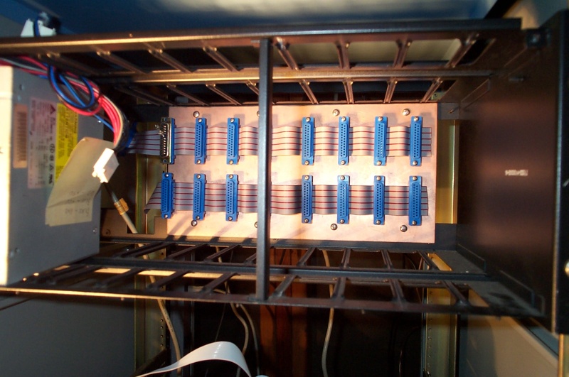
The cage had eight slots, so we put a pair of DB-25s for each one. (In this picture one pair is hidden by the support bar.) The top cable extended to the left and had an additional DB-25 plugging into the power supply. We later found out that one of the pins on the bus should have been grounded but wasn't, so we hacked a DB-25 to plug into the left-most slot. (It's slightly out of focus in the picture, but it's just a pull-up resistor.)
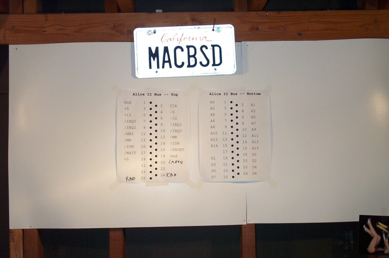
The bus itself was made of a top and a bottom part. The top bus consisted of the power and control pins, while the bottom bus was used for address and data. We created often-referred-to reference cards on poster paper which we kept on the wall of the garage.
Top Bus
- Pin 1 - Gnd
- Ground wire. We later added pin 18 for the same purpose to make sure we could carry all the current.
- Pin 2 - Clk
- Clock signal, generated by the clock board.
- Pin 3 - +5V power
- This pin was used to power the whole computer, and we later added pin 19 to supplement it.
- Pin 4 - -5V power
- Pin 5 - +12V power
- Pin 6 - -12V power
- Pin 5 - +12V power
- Not hooked up or used.
- Pin 7 - /IRQ0
- Pin 8 - /IRQ1
- Pin 9 - /IRQ2
- Pin 10 - /IRQ3
- Pin 8 - /IRQ1
- These four pins were active-low interrupt request signals. They were plugged into the CPU board's 8259 interrupt controller.
- Pin 11 - /NMI
- The active-low non-maskable interrupt line wasn't used, although I think it was plugged into the CPU. A non-maskable interrupt cannot be turned off in software. It's usually used for emergencies, such as a warning that power is about to go out.
- Pin 12 - /MR
- Pin 13 - /MW
- Pin 14 - /IOR
- Pin 15 - /IOW
- Pin 13 - /MW
- Active-low memory read/write and I/O read/write. The CPU asserts these pins when it wants to access memory or an I/O port. The CPU's four pins are actually memory request, I/O request, read, and write, and we converted those to our four because we figured that it would be easier to decode on boards. That turned out to be a bad idea—see pin 20 for the explanation.
- Pin 16 - /RESET
- Active-low reset. There was a reset button both on the clock board and on the LCD box.
- Pin 17 - /WAIT
- Active-low wait line. The wait line is activated by memory to tell the CPU to wait a couple cycles. I don't think we ever hooked it up to anything.
- Pin 18 - Gnd
- Pin 19 - +5V power
- We added these to make sure the boards had enough power.
- Pin 20 - /MREQ
- It turns out that the CPU's memory request pin and the read/write pins aren't asserted at the same time. /MREQ gets asserted first, the address pins are set, there's a short delay, then /RD or /WR is asserted. The short delay lets the address pins settle before a read or write is executed. With our original system, /MREQ and /RD or /WR were ANDed together on the CPU board, so the memory board had no chance of letting the address pins settle, leading to bad reads and writes. We had to add /MREQ to solve this problem.
- Pin 24 - Kbd
- Pin 25 - Kbd
- The LCD box (into which the keyboard was plugged) used these two lines to send keystroke events to the I/O board.
Bottom Bus
Pins 1 through 16 held A0 through A15, and pins 18 through 25 held D0 through D7.